Project 03: Art Project
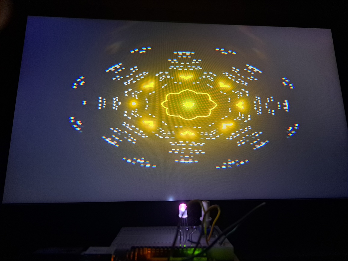
This project was pretty fun to do, however, I did get heavily side tracked trying to perfect it as much as possible, and completely messed up time management for the project. However, I’m quite happy with the final result, and I think it looks really cool.
The Circuit
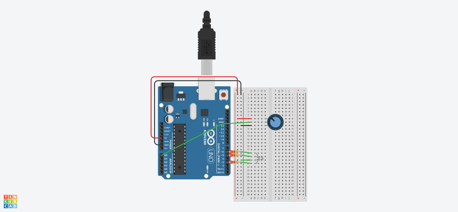
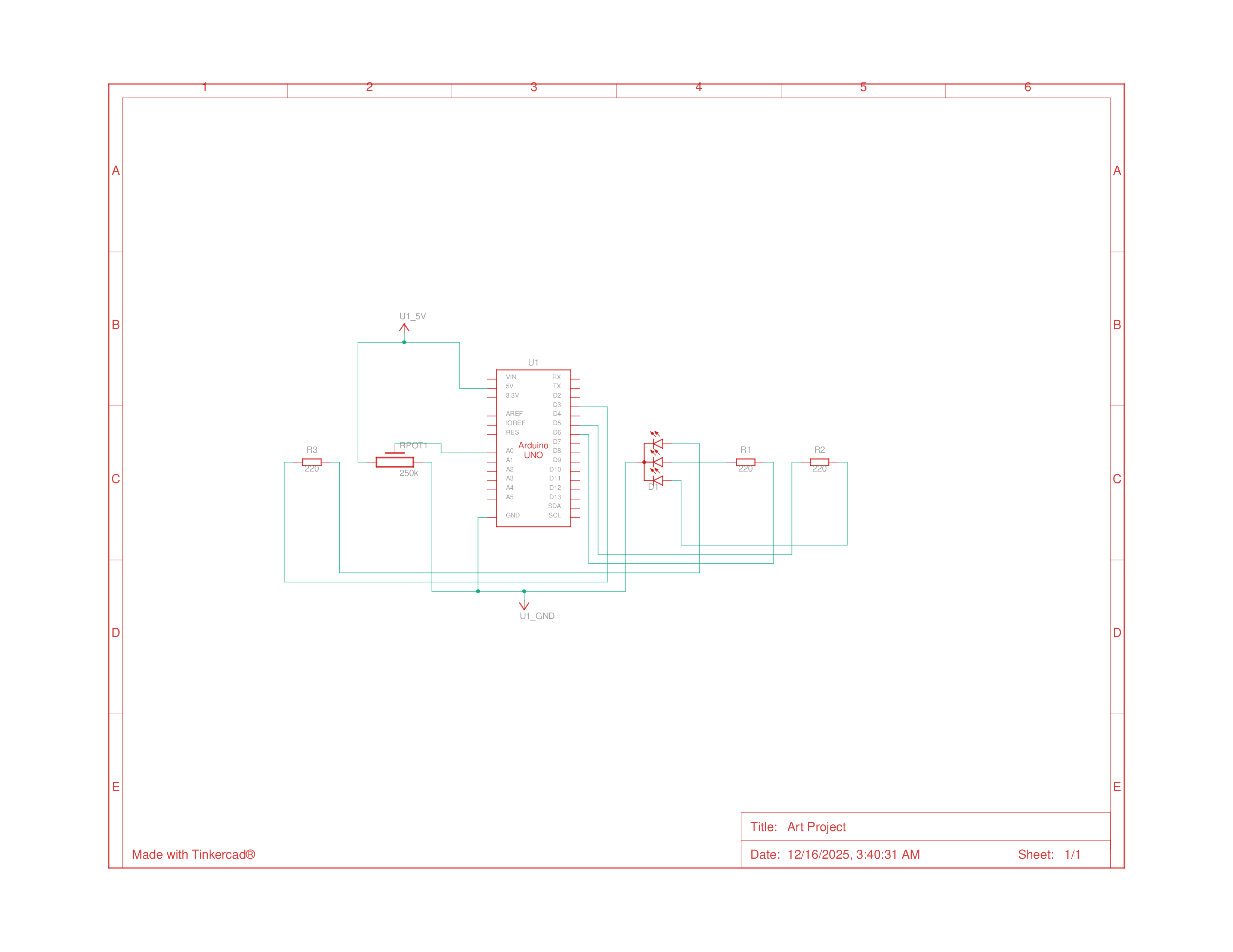
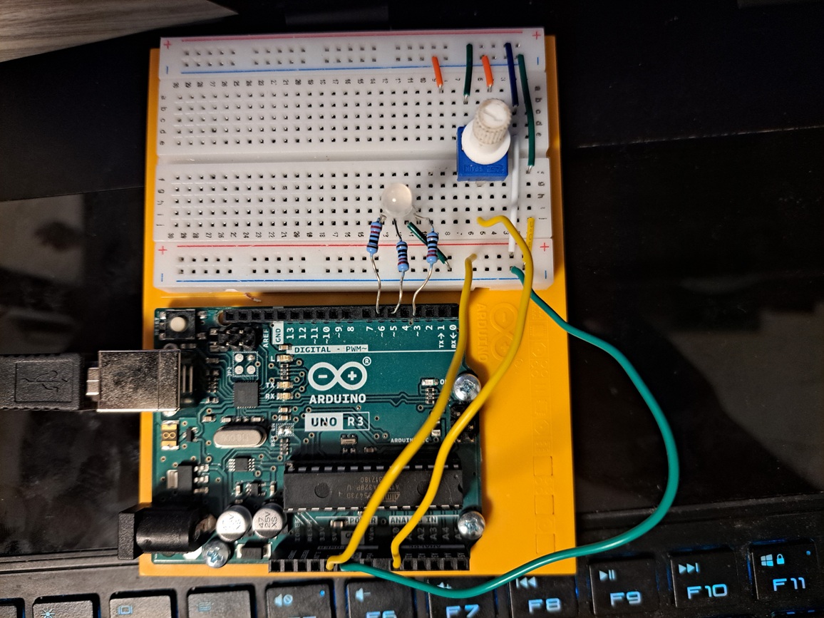
The circuit for this was pretty simple, just a potentiometer and RGB LED
Parts List
| Name | Quantity | Component |
|---|---|---|
| U1 | 1 | Arduino Uno R3 |
| Rpot1 | 1 | 250 kΩ Potentiometer |
| R2, R3, R1 | 3 | 220 Ω Resistor |
| D1 | 1 | RCBG LED RGB |
Schematics
Building the Circuit
Programming the Arduino
After constructing the circuit, I wrote the code for the Arduino. Similarly to Diver, all the Arduino needed to do for this project was to communicate its data to the SerialPort so that I could have full control over how to interpret it in Unity, additionally, it needed to reed the incoming data from unity to set the colors on the rgb, and because I had to do an additional step of parsing floats from unity, the code is slightly more complicated, but it’s still relatively simple.
Code
1
2
3
4
5
6
7
8
9
10
11
12
13
14
15
16
17
18
19
20
21
22
23
24
25
26
27
28
29
30
31
32
33
34
35
36
37
38
39
40
41
42
43
44
45
46
47
48
49
50
51
52
53
54
55
56
57
58
59
60
61
62
63
64
65
const int potPin = A0;
const int redPin = 3;
const int greenPin = 6;
const int bluePin = 5;

int potData = -1;
char buffer[20];
byte index = 0;

void setup() {
  // initialize serial communication
  Serial.begin(9600);

  // assign led pins
  pinMode(redPin, OUTPUT);
  pinMode(greenPin, OUTPUT);
  pinMode(bluePin, OUTPUT);
}

// data processing wll be done by Unity
// just bus raw values to serial port as soon as possible,
// and use raw values from serial port
void loop() {
  // read data
  potData = analogRead(potPin);

  // write data to serial port
  Serial.println(potData);

  // If there is data in the serial port, read it
  while (Serial.available() > 0) {
    // reads all available bytes
    char c = Serial.read();

    // process rgb value on end of line
    // --Doesn't update led until full RGB line is sent
    if (c == '\n') {
      buffer[index] = '\0';
      parseRGB(buffer);
      index = 0;
    }
    // Store character if buffer not full
    else if (index < sizeof(buffer) - 1) {
      buffer[index++] = c;
    }
  }
}

void parseRGB(char* data) {
  int r = 0, g = 0, b = 0;

  // splits incoming string into rgb values
  char* token = strtok(data, ",");
  if (token) r = atoi(token);
  token = strtok(NULL, ",");
  if (token) g = atoi(token);
  token = strtok(NULL, ",");
  if (token) b = atoi(token);

  // sets values as given from data stream
  // Only processing is keeping it in range from 0-255
  analogWrite(redPin, constrain(r, 0, 255));
  analogWrite(greenPin, constrain(g, 0, 255));
  analogWrite(bluePin, constrain(b, 0, 255));
}
Programming the Visualization
After I finished programming the Arduino, it was time to make the visualization. This took a while to get right, I did a lot of fine tuning with the particle graphs to create effects I thought looked cool. I ended up with 4 (technically 3) different graphs that run at the same time:
- 2 line graphs that draw trails in opposite directions from each other
- A fireworks graph to draw burst of particles that curst out of each other
- A simple particle graph that draws burst of particles
Additionally, I wrote a kaleidoscope shader that mirrors the top left fraction of the screen n-times, the Arduino controls the number, and I limited it from 1-24 which is the range I found that looked nice.
The last bit I was proud of figuring out how to do was getting the most prominent color from the screen, and sending that to the RGB LED, which I took a while to figure out.
Challenges
Aside from time-management which I completely failed at for this project, I ran into issues with enabling HDR colors in my particle systems and using them in shader graph to get the bloom effects to work right. This was just an engine bug that I spent lots of time debugging, and was ultimately fixed by just relaunching the project the next day.
Other issues were that trying to assign a new Render Feature in unity to use my kaleidoscope shader was super complicated for no reason, the official documentation gives you multiple low level ways to do it, where you have to create a custom render pass and do all sorts of other things to register the shader you wrote to it. I couldn’t quite get that to work, but with enough tinkering, I was able to just use the built in shader graph and register a full screen render pass to the Global volume object to create the effect. I have no idea why the documentation doesn’t just lead with that being a simple fast way to do it, rather than burying it in the depths of specific sections for seemingly unrelated things.
The last challenge I had was getting the most prominent color from the screen, since because graphics is complicated, you can’t just grab the output texture and just loop through all the pixels. I had struggled with using their documentation to create a semi-custom render pass to output to 2 buffers and try use that to get an average color, however, that whole process ended up being wasted effort and me just over-complicating things. I had eventually figured out that I could just make another camera and have it render to a render texture object which could store the render data I was trying to get from the ‘main’ camera. This also helped me with performance since I could render to a lower resolution and so it was easier to find the most prominent color that way
Code
The repo and the rest of the code can be found here: https://github.com/SamayRShah/ArtProject
The Arduino related code is pretty much the same as the previous diver project, only this time there was no added UI navigation stuff, and the only data captured from the Arduino is the potentiometer position. Additionally, instead of just passing in a string ‘1’ or ‘0’ to the data stream, it passes in the rgb values as a string.