Homework 15: Hacking Buttons
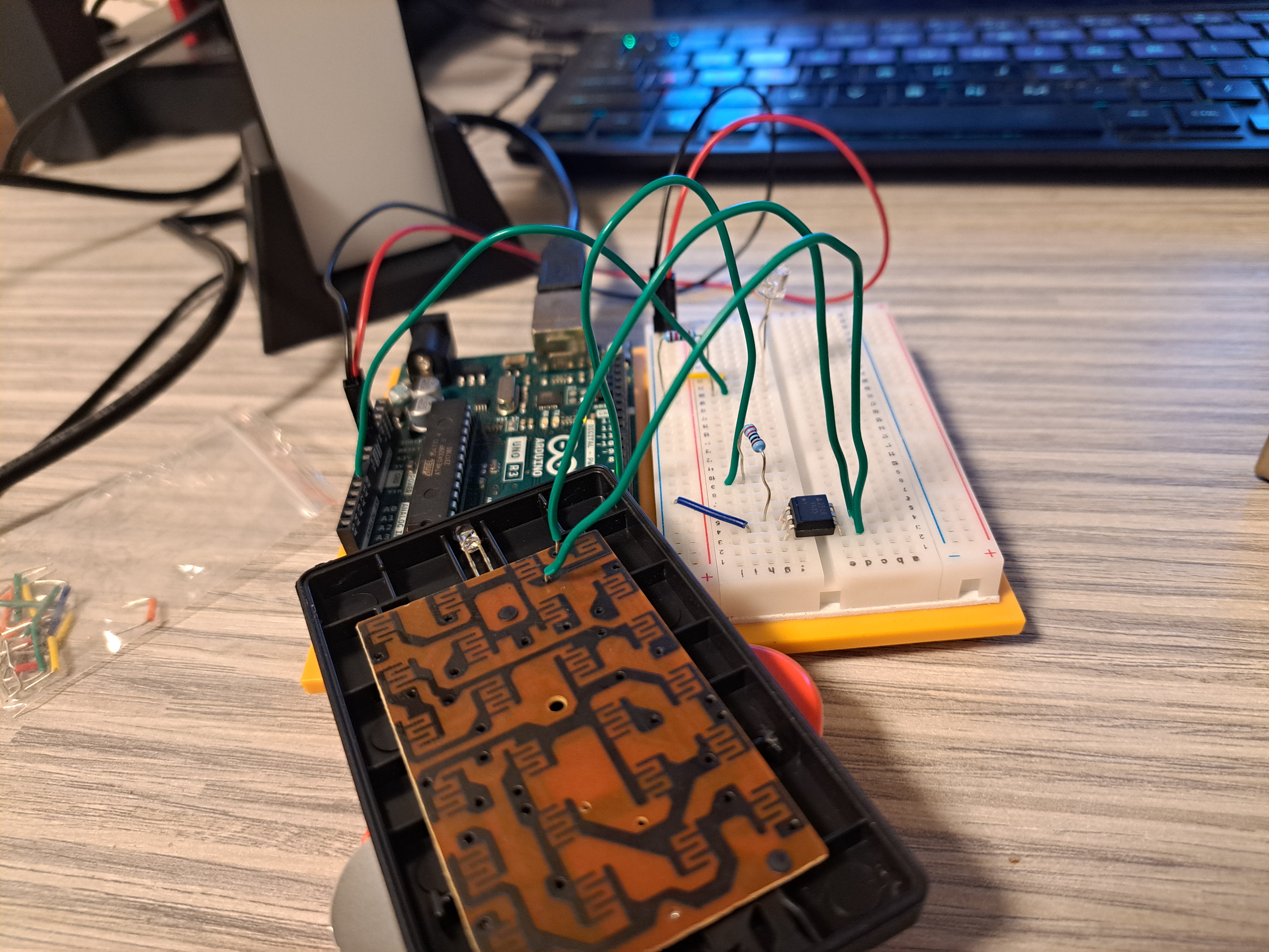
The Circuit
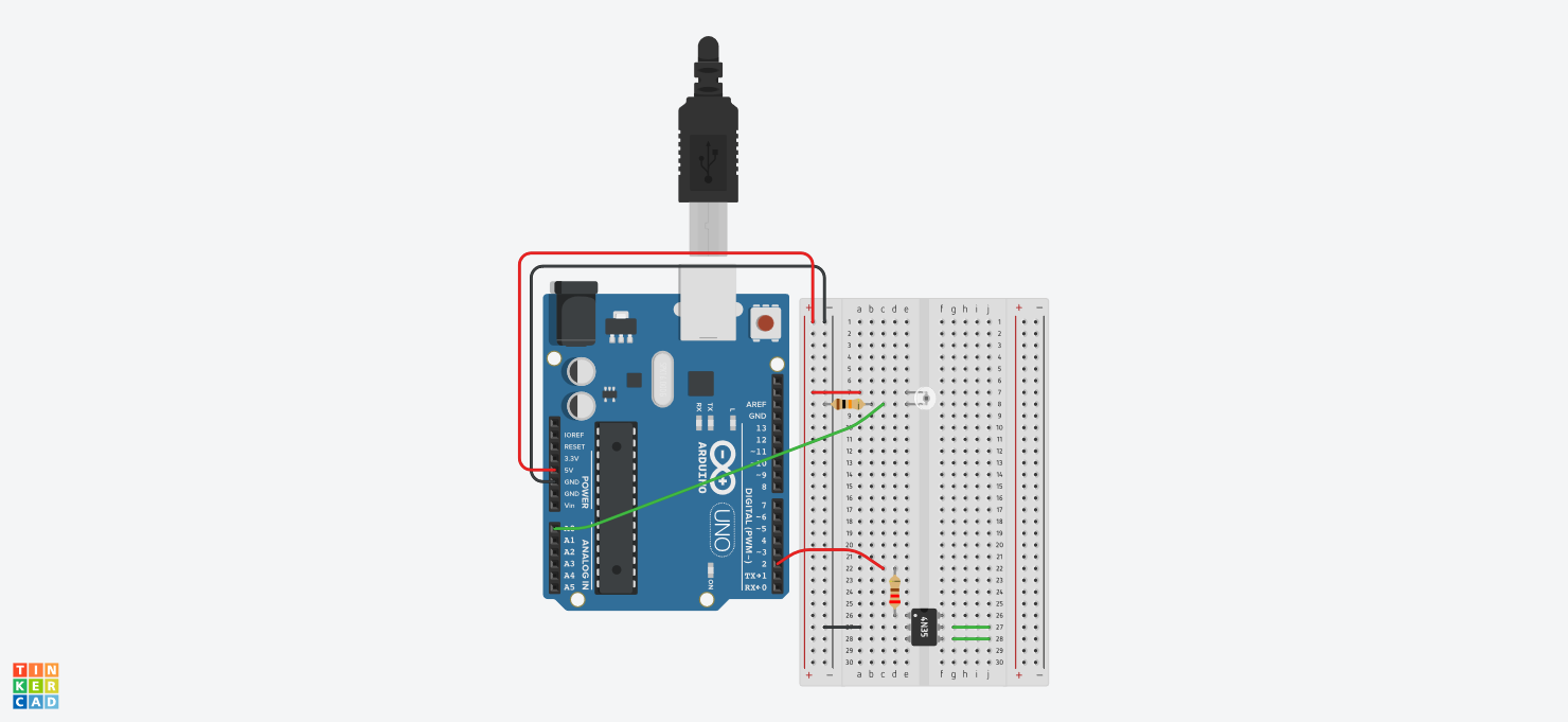
Parts List
| Name | Quantity | Component |
|---|---|---|
| U1 | 1 | Arduino Uno R3 |
| Q1 | 1 | Ambient Light Sensor [Phototransistor] |
| R1 | 1 | 10 kΩ Resistor |
| U2 | 1 | Optocoupler |
| R2 | 1 | 220 Ω Resistor |
Schematics
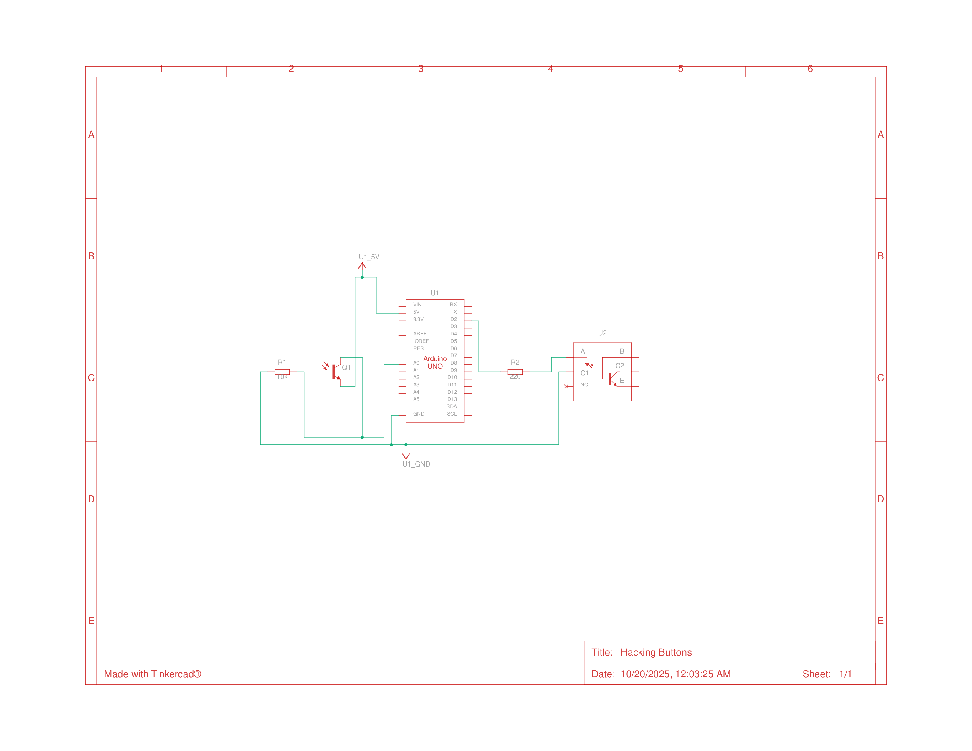
Building the Circuit
This circuit was more interesting to create this time since there was a bit more creative freedom in terms of the sensors we were using or what we were connecting to. I opted to use a light sensor to turn on the LED bar when the lights turn off. I
The part that I was most hesitant about in this was taking apart the remote and wiring the arduino to it, and to connect the wires, I just used tension to hold the wires to the circuit since I was planning on putting the remote back together after I was done with the project.
Programming
After constructing the circuit, I began writing the code, which was easy enough with all the experience I had from the previous project. I just checked if the light value was below a threshold, at which point send power to the pin to turn on the remote through the optocoupler.
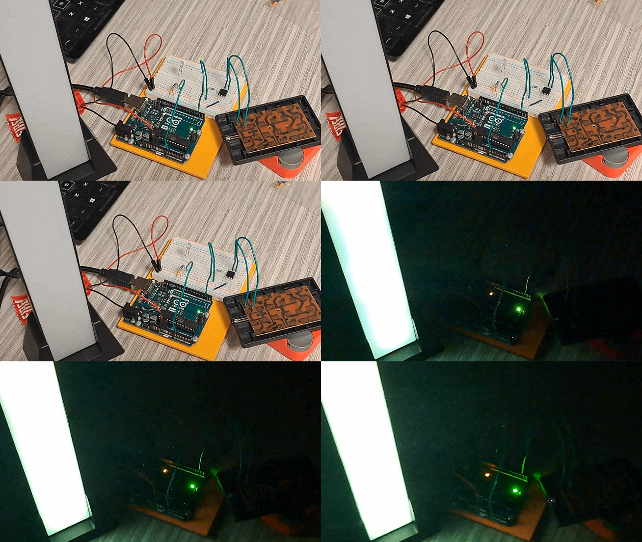
Doing this project made electronics seem simpler to me and demystified how things worked, and made me less hesitant about having to take things apart and fixing them myself.
Code
One thing you might notice when examining the code is that there is no code to turn the LEDs off when lights turn on, I didn’t add that code since the on and off buttons are wired separately on my remote, and I didn’t want to bother wiring up more optocouplers and controls for a temporary project. If I were to make things more permanent I would probably spend more time connecting things, and I would also wire the other controls, but for now it only turns the LED on when it gets dark, and to turn it off you just have to connect the ‘forks’ with another wire.
1
2
3
4
5
6
7
8
9
10
11
12
13
14
15
16
17
18
19

const int optoPin = 2;  // the pin the optocoupler is connected to
const int sensorLow = 10; // light turn on threshold
int sensorValue;

void setup() {
  // make the pin with the optocoupler an output
  pinMode(optoPin, OUTPUT);
}

void loop() {
  sensorValue = analogRead(A0);
  if(sensorValue < sensorLow){    // check if light is under threshold
    digitalWrite(optoPin, HIGH);  // activate the optocoupler
    delay(15);  // give the optocoupler a moment to activate
    digitalWrite(optoPin, LOW);  // pull pin 2 low until you're ready to activate again
  }
}