Homework 12: Knock Lock
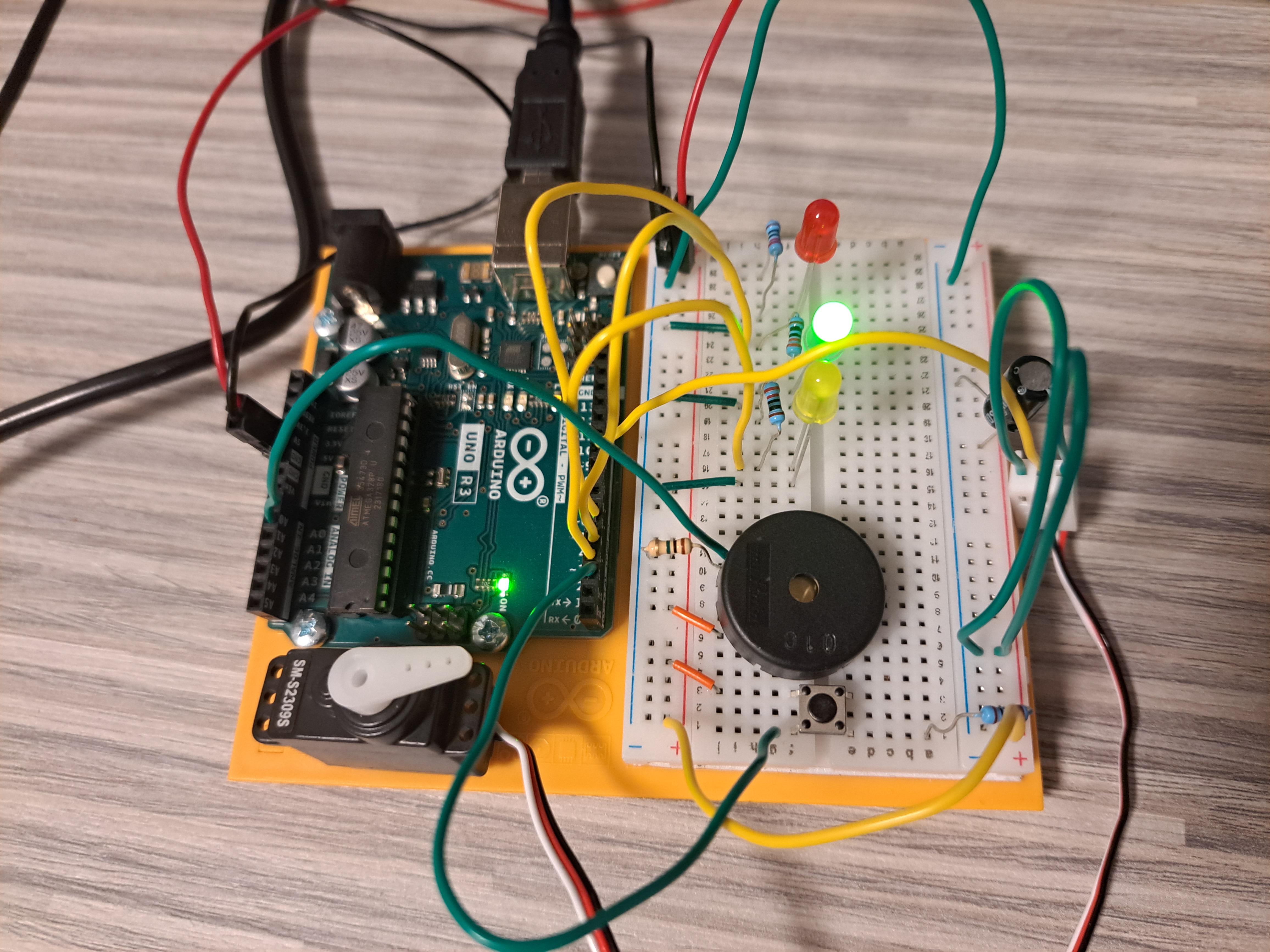
The Circuit
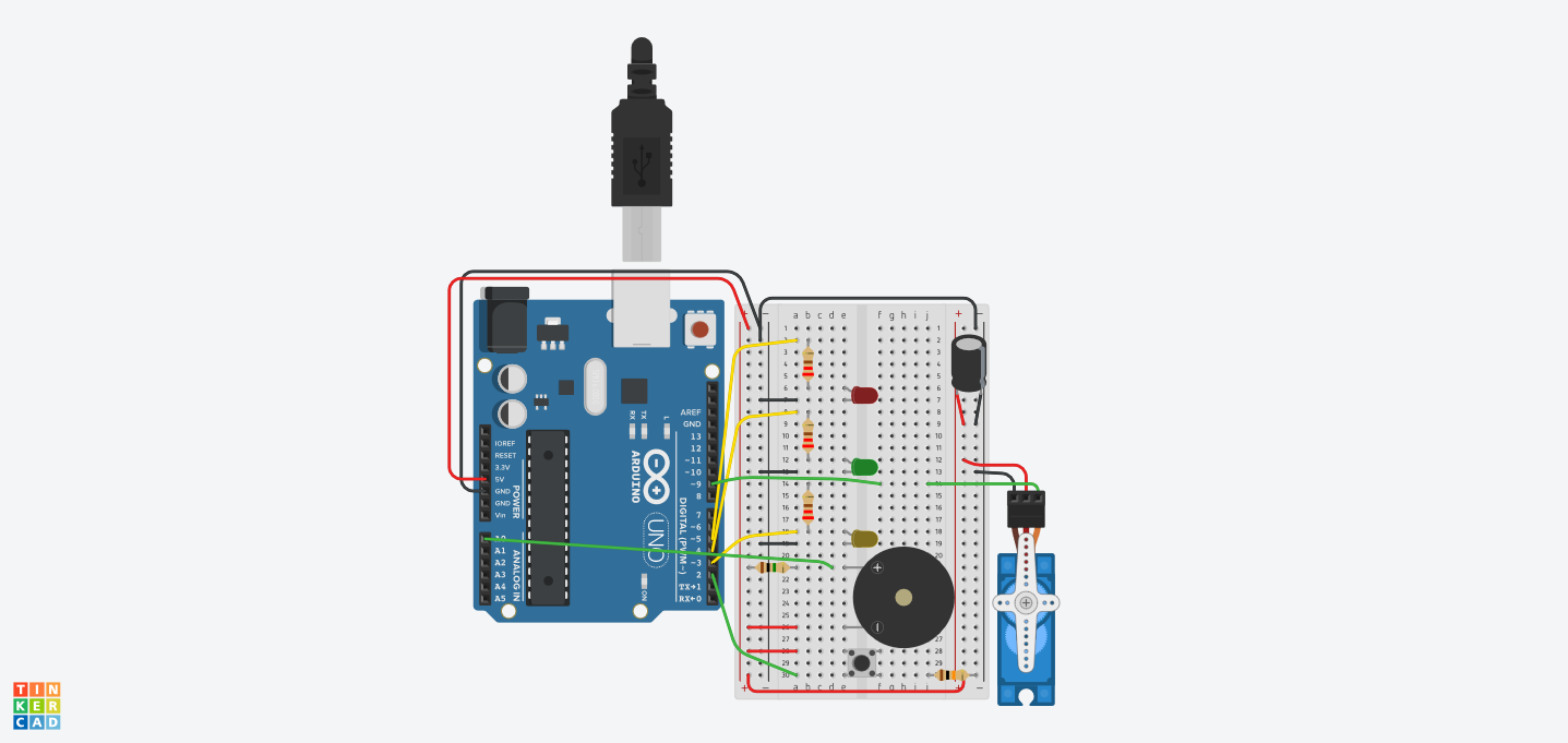
Parts List
| Name | Quantity | Component |
|---|---|---|
| U1 | 1 | Arduino Uno R3 |
| R1, R2, R3 | 3 | 220 Ω Resistor |
| D1 | 1 | Red LED |
| D2 | 1 | Green LED |
| D3 | 1 | Yellow LED |
| PIEZO1 | 1 | Piezo |
| S1 | 1 | Pushbutton |
| R4 | 1 | 10 kΩ Resistor |
| SERVO1 | 1 | Positional Micro Servo |
| C1 | 1 | 1 uF, 16 V Polarized Capacitor |
| R5 | 1 | 1 MΩ Resistor |
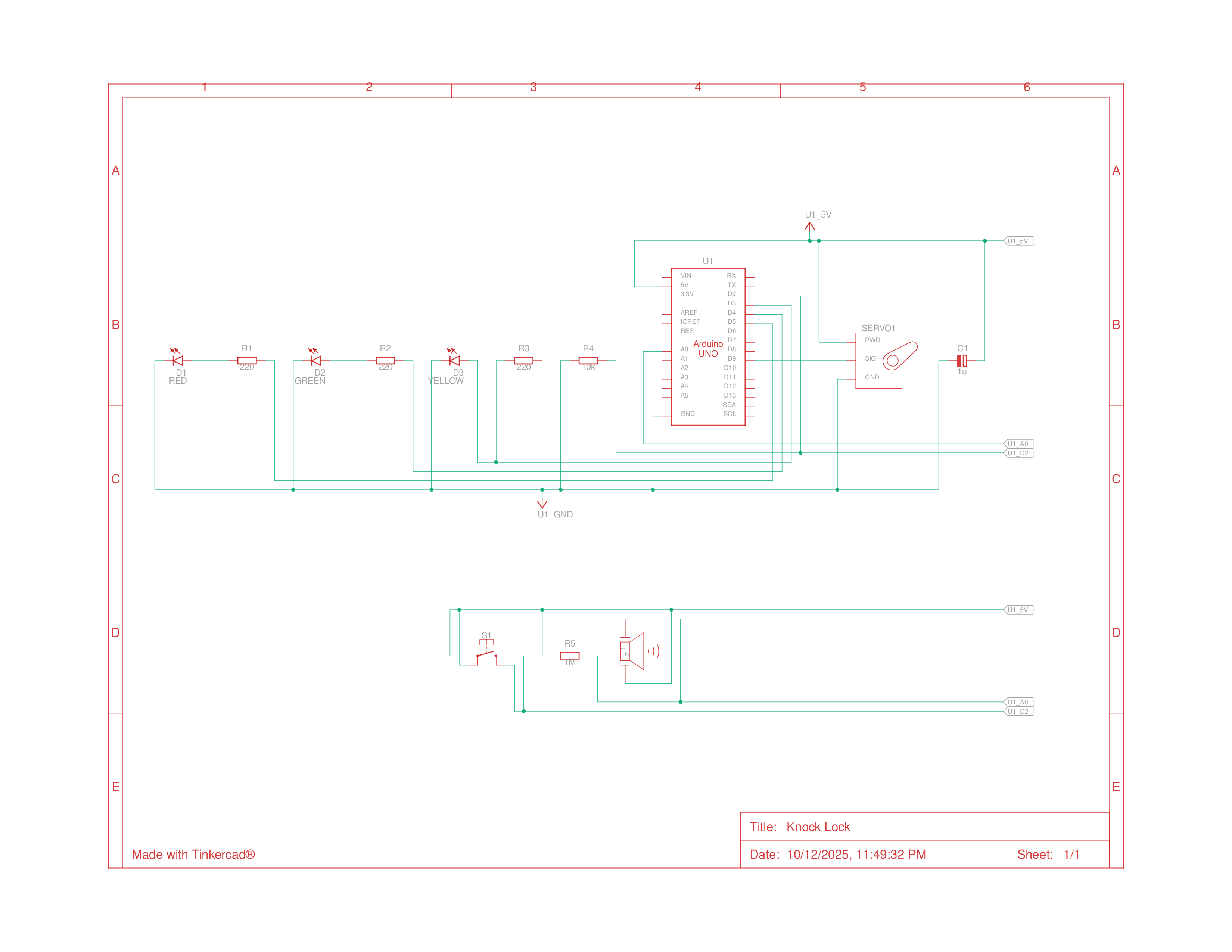
Schematics
Building the Circuit
Building the circuit went by quickly and I don’t really have much more to say about it. I assembled it, loaded the sketch, and it worked fully. One thing I did change in the example sketch was that I added another small delay after the yellow LED went off as more user feedback for accepting a valid knock. It also gave the Piezo time to settle since without the delay, it would register reverberations from the same lock twice, so it could be unlocked with just 1 knock.
Programming
After confirming that the circuit was working, I then unloaded the example sketch and began programming the arduino. The code this time was a bit more complex and I started getting a feel for how more and more complexity stacks with more components, and it was cool to see the piezo having its uses reversed.
1
2
3
4
5
6
7
8
9
10
11
12
13
14
15
16
17
18
19
20
21
22
23
24
25
26
27
28
29
30
31
32
33
34
35
36
37
38
39
40
41
42
43
44
45
46
47
48
49
50
51
52
53
54
55
56
57
58
59
60
61
62
63
64
65
66
67
68
69
70
71
72
73
74
75
76
77
78
79
80
81
82
83
84
85
86
87
88
89
90
91
92
93
94
95
96
97
98
99
100
101
102
103
104
105
106
107
108
#include <Servo.h>
Servo myServo;

const int piezo = A0;
const int switchPin = 2;
const int yellowLed = 3;
const int greenLed = 4;
const int redLed = 5;

int knockVal;
int switchVal;

// variables for the high and low limits of the knock value
const int quietKnock = 10;
const int loudKnock = 100;

// variable to indicate if locked or not
bool locked = false;
int numberOfKnocks = 0;

void setup() {
  myServo.attach(9);

  // make the LED pins outputs
  pinMode(yellowLed, OUTPUT);
  pinMode(redLed, OUTPUT);
  pinMode(greenLed, OUTPUT);

  // set the switch pin as an input
  pinMode(switchPin, INPUT);

  // start serial communication for debugging
  Serial.begin(9600);

  // start with 'door' open
  digitalWrite(greenLed, HIGH);
  myServo.write(0);
  Serial.println("the box is unlocked!");
}

void loop() {
  if (!locked) {
    switchVal = digitalRead(switchPin);

    if (switchVal == HIGH) {
      locked = true;

      // change the status LEDs
      digitalWrite(greenLed, LOW);
      digitalWrite(redLed, HIGH);

      // move the servo to the locked position
      myServo.write(90);
      Serial.println("the box is locked!");
      delay(1000); // wait for servo to move
    }
  }

  if (locked) {
    knockVal = analogRead(piezo);

    // if there are not enough valid knocks
    if (numberOfKnocks < 3 && knockVal > 0) {
      if (checkForKnock(knockVal)) numberOfKnocks++;

      // print status of knocks
      Serial.print(3 - numberOfKnocks);
      Serial.println(" more knocks to go");
    }

    // if there are three knocks
    if (numberOfKnocks >= 3) {
      // unlock the box
      locked = false;
      // move the servo to the unlocked position
      myServo.write(0);
      delay(20);

      // change status LEDs
      digitalWrite(greenLed, HIGH);
      digitalWrite(redLed, LOW);
      Serial.println("the box is unlocked!");

      numberOfKnocks = 0;
    }
  }
}

// checks if detected knock is within range
bool checkForKnock(int value) {
  if (value > quietKnock && value < loudKnock) {
    // turn the status LED on
    digitalWrite(yellowLed, HIGH);
    delay(50);
    digitalWrite(yellowLed, LOW);
    delay(50);

    Serial.print("Valid knock of value ");
    Serial.println(value);
    return true;
  }
  else {
    // print status
    Serial.print("Bad knock value ");
    Serial.println(value);
    return false;
  }
}