Homework 4: Color Mixing Lamp
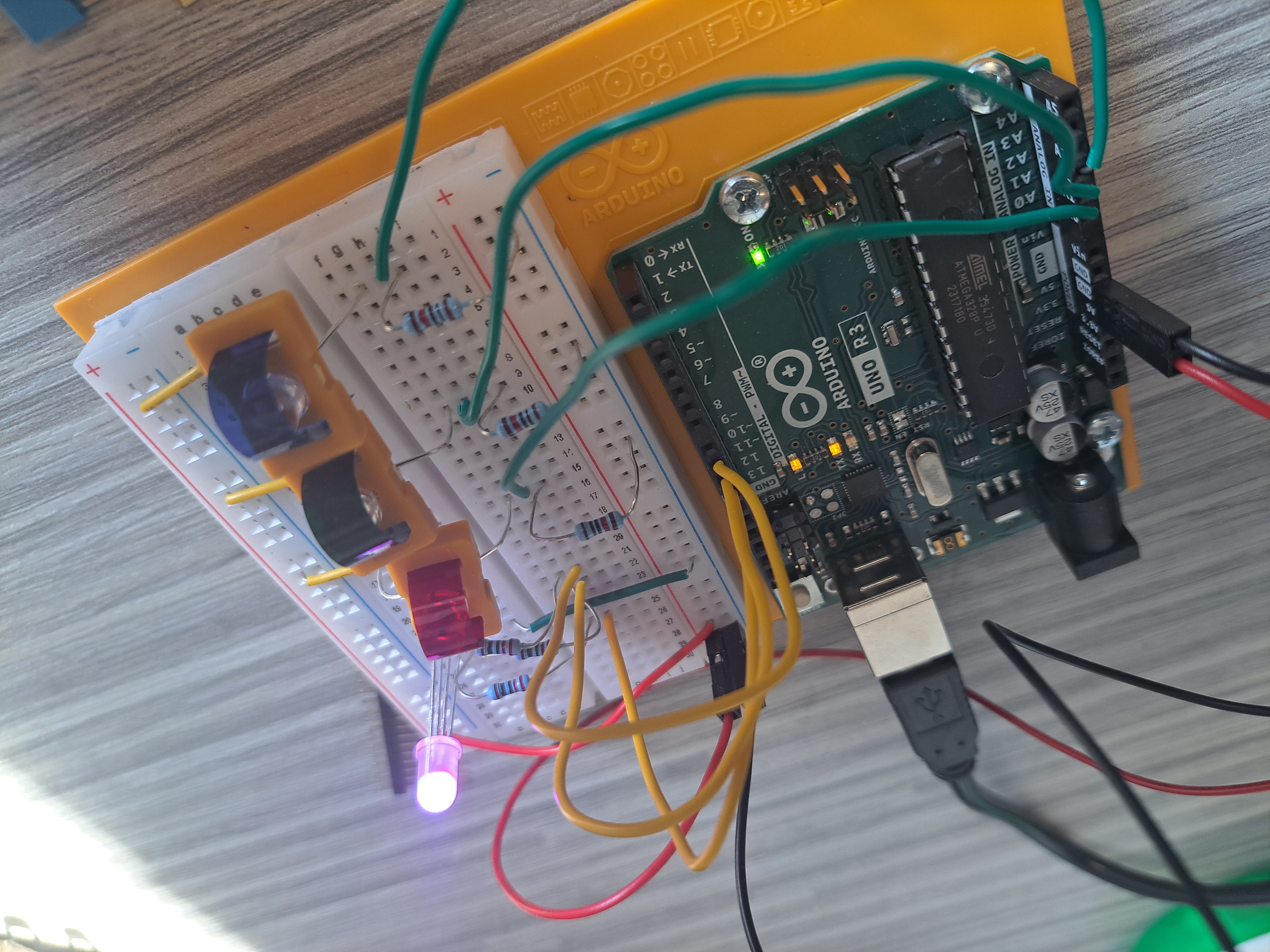
This project was pretty cool, where I started using the RGB LED component and did more with analog sensors. I also used Tinkercad to build the circuit and simulate it in advance before starting to build it myself. Whilst it may not be super useful at the moment, I can see how it would be useful for debugging and testing circuits once I start building my own things instead of following the book, especially since you can also simulate the code running.
The Circuit
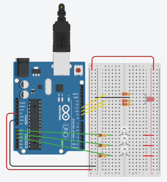
Parts List
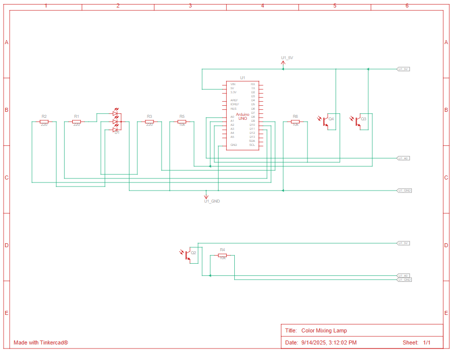
| Name | Quantity | Component |
|---|---|---|
| U1 | 1 | Arduino Uno R3 |
| D1 | 1 | RCBG LED RGB |
| R1, R2, R3 | 3 | 220 Ω Resistor |
| Q2, Q3, Q4 | 3 | Ambient Light Sensor [Phototransistor] |
| R4, R5, R6 | 3 | 10 kΩ Resistor |
Schematics
Building the Circuit
This time building the circuit was especially finicky since there were lots of small pieces, and the gels kept exploding out of the plastic holders that came with the starter kit.
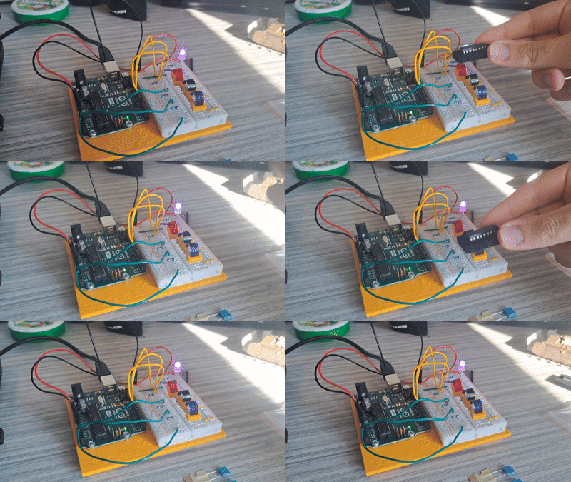
After that, I loaded the Color Mixing Lamp sketch in the Arduino IDE, and it worked.
Programming
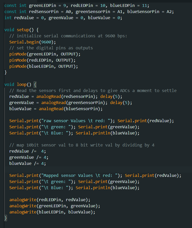
After confirming that the circuit was working, I began writing the code for the project. The code was pretty straight forward, though one thing I did notice and didn’t realize was needed was that there are delays in between sensor readings to give it time for the ADC to stabilize.