Homework 5: Mood Cue
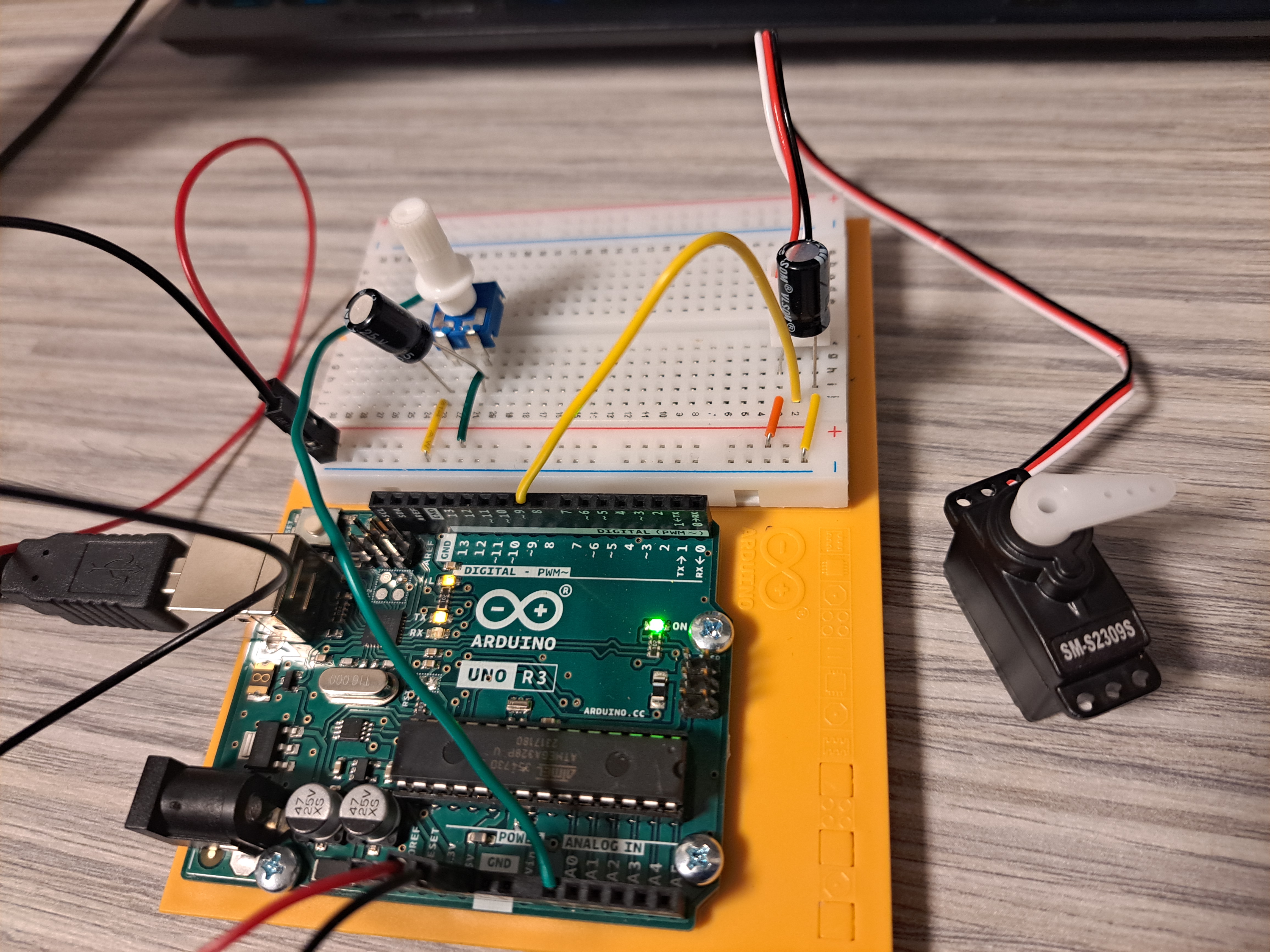
I enjoyed this project more because the circuit building was straight forward without any small components that go flying at the slightest touch, and getting to use servos to see things move. The only other thing I have to say about this project is that I couldn’t be bothered to build the mood cue paper cutouts since I was short on time and I was going to disassemble the project right after doing the writeup anyways.
The Circuit
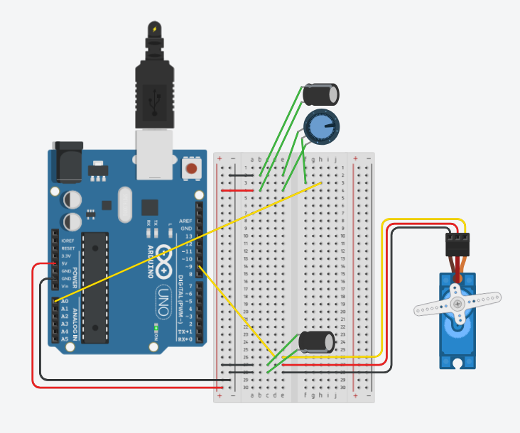
Parts List
| Name | Quantity | Component |
|---|---|---|
| U1 | 1 | Arduino Uno R3 |
| C1, C2 | 2 | 100 uF, 16 V Polarized Capacitor |
| Rpot4 | 1 | 250 kΩ Potentiometer |
| SERVO1 | 1 | Positional Micro Servo |
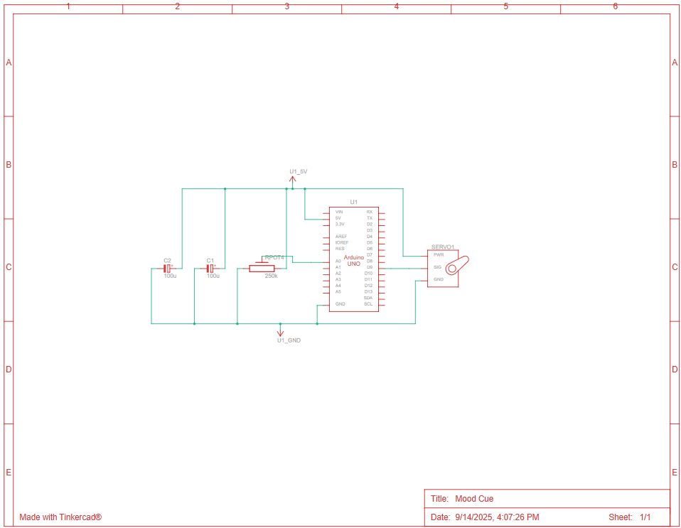
Schematics
Building the Circuit
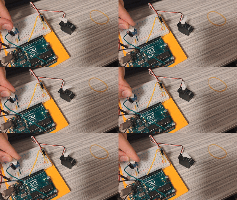
There isn’t much to say about building the circuit since all I did was follow the book, though I did pay more attention when placing and connecting the capacitors since there was a risk of exploding. After that, I loaded the Mood Cue sketch in the Arduino IDE, and it worked.
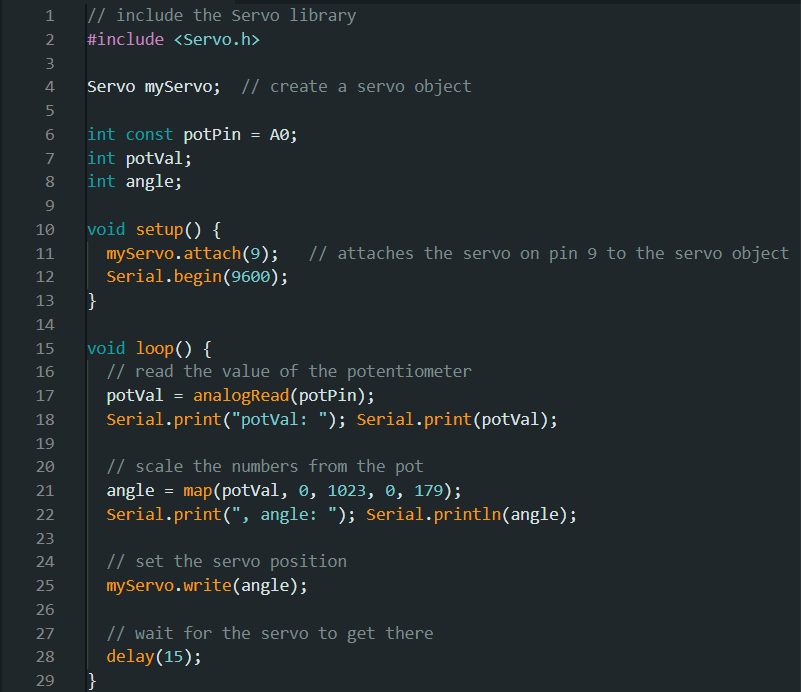
Programming
After confirming that the circuit was working, I began writing the code for the project. The code was super simple and straight forward, but it did introduce importing libraries which was new. Programming this also brought to my attention the fact we were programming physical components that have processes that we have to wait for, like adding delay to wait for the servo to move.